Until recently phased array radar has been very expensive, used only for military applications where the cost of survival weighs in the balance. With the advent of low-cost microwave devices and unconventional architecture phased array radar is now within the reach of the hobbyist and consumer electronics developer. In this post we will review the basics of phased-array radar and show examples of how to make low-cost short-range phased array radar systems — I built the one seen here in my garage! Sense more with more elements by making phase array your next radar project.
Phased array radar
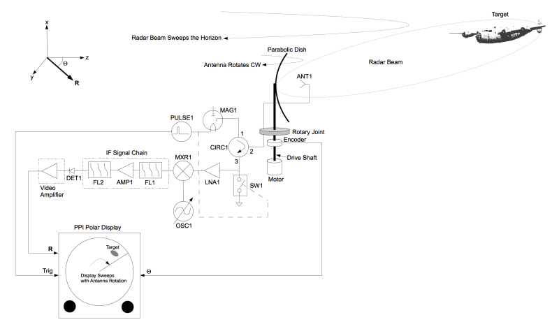
In a previous post the basics of radar were described where a typical radar system is made up of a large parabolic antenna that rotates. The microwave beam projected by this antenna is swept over the horizon as it rotates. Scattered pulses from targets are displayed on a polar display known as a Plan Position Indicator (PPI).
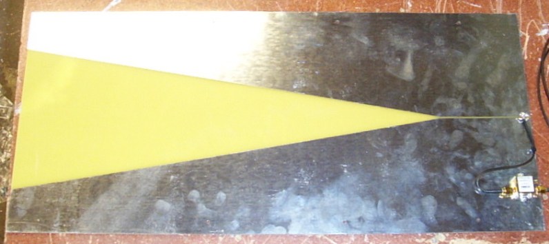
In a phased array radar (PDF) system an array of antenna elements are used instead of the dish. These elements are phase-coherent, meaning they are all phase-referenced to the same transmitter and receiver. Each element is wired in series with a phase shifter that can be adjusted arbitrarily by the radar’s control system. A beam of microwave energy is focused by applying a phase rotation to each phase shifter. This beam can be directed anywhere within the array’s field of view. To scan the beam rotate the phases of the phase shifters accordingly. Like the rotating parabolic dish, a phased array can scan the horizon but without the use of moving parts.
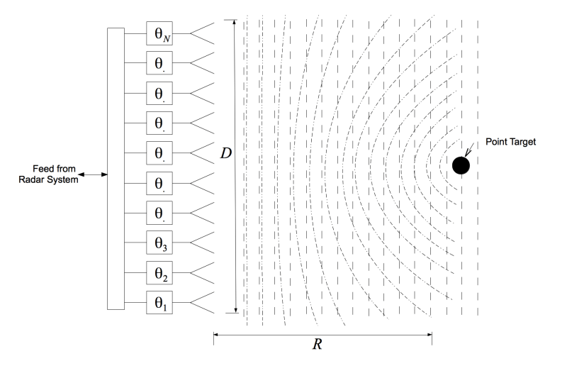
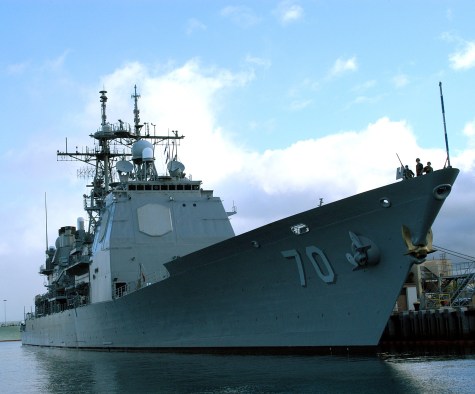
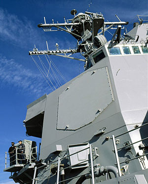
To scan the entire horizon you often will need 4 or more arrays. This is why the SPY-1 radar uses 4 panels directed fore, aft, port, and starboard.
Phased array radars at short ranges
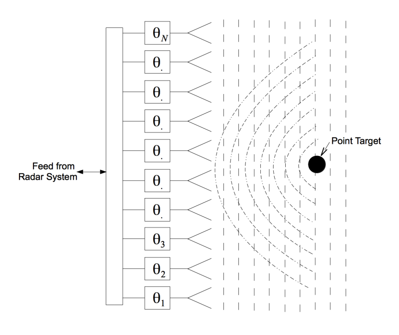
Long-range phased array radar systems focus their microwave beams in the far field using relatively simple phasing techniques to steer the beam. Most radar arrays that we might build for hobbyist or consumer applications will be operating at short ranges using low-cost wide-band microwave radar devices. At these short ranges radar targets are often in the near-field where it becomes difficult to focus the antenna beam using conventional far-field methods without accounting for wavefront curvature.
When a wave of any kind is emitted from a source it travels outwards in a spherical pattern. At long distances this sphere appears planar (e. g. a plane wave) as the spherical wave spreads out as it radiates away from the source antenna.
There are several ways to account for wavefront curvature at short-ranges. You can apply a parabolic phase function to each of your phase shifters or you can receive (or transmit) with each element independently and back-out the wavefront curvature in software. There are many ways to achieve this all of which depart from the traditional phased array architectures.
Unfortunately using numerous digitizers at useful bandwidths for radar continues to be prohibitively expensive for consumer products and the hobbyist when a design requires 50, 100, 1000, or 5000 elements. If you are willing to trade acquisition time for cost you could implement a much less expensive near-field array using switching techniques. In this post we’ll discuss three examples of switched-array radar systems.
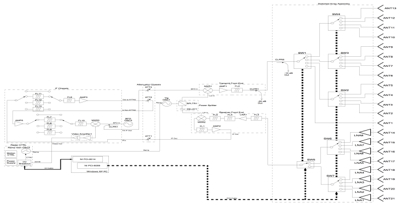
In a switched array system the transmit and receive ports of one low-cost radar sensor are switched (or multiplexed) across an array of antenna elements using microwave switches. Data from each combination of transmit and receive elements is digitized and stored where focusing (or image reconstruction) is computed in the digital domain. This method can support frame rates of 10, 20, or even 40 FPS. Specific examples of this technique are shown below.
Prototype thru-wall radar
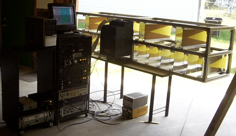
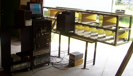
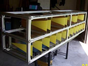
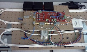
Anyone can build a switched array radar system. Here is an example of one built in my garage from 80/20 aluminum and some Mini-Circuits components. The size of the array was set by the longest 6 pieces of 80/20 I could find at the local junk yard, which were 8’3”. In this system I multiplexed the transmitter port and receiver port across 13 and 8 antennas respectively. The switching sequence allows for the phase center of this radar to be electronically moved down its length for a total of 44 effective radar Transmit/Receive pairs. I used a Synthetic Aperture Radar (SAR) algorithm that accounts for wavefront curvature to form the imagery.
The purpose of this radar was to prove the concept of imaging through concrete walls at stand-off ranges. It could image (by image I mean display a small red blob at a top-down view of what is on the other side of the wall) a 12 oz soda can through a 4” thick concrete wall at a stand-off range of 20′, not bad for a garage-built system.
From garage to the MIT through-wall radar
While at MIT Lincoln Laboratory I convinced two of my colleagues, [John Peabody] and [Tyler Ralston], to join me in making a high performance through-wall imaging system. This one achieved 11 FPS and could image through 4”, 8”, and ‘cinder block’ walls with ease.
This project that originated in the garage won Best Paper at the Tri-Services Radar Symposium in 2010. Academic papers with details can be found here.
MIT professional education/IAP array radar
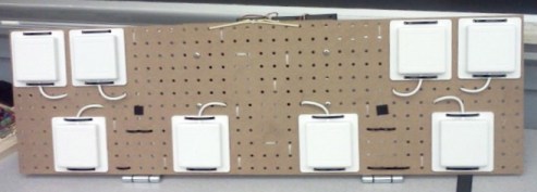
Given the interest in the MIT coffee can radar course, I worked with colleagues at Lincoln Laboratory to develop a phased array course. To make the low-cost student built radar kits we added a pair of microwave switches and used a switched-array layout nearly identical to the thru-wall radar. These phased array radar devices were assembled using pegboard and WiFi antennas. The latest iteration of this radar device achieved 20 FPS. Anyone can build a phased array radar with WiFi antennas and pegboard.
Where to learn more:
- The largest phased array symposium in the world is held every 3 years, the IEEE International Symposium on Phased Array Systems and Technology 2016. Like most IEEE events admission is fairly inexpensive and a student program will be available. There will be numerous tutorial sessions (short-courses) on phased array radar design and implementation.
- One of the most well know advocates for phased array radar technology is [Eli Brookner].
- Switched-array radars are discussed in detail in my book Small and Short-Range Radar Systems.
Summary
Phased arrayed radar has been very expensive and is traditionally used in state-of-art air defense systems but today you can make your own at short-ranges. Try phased array radar for your next project, sense or image something fast, accurately, and without moving parts.
Author Bio
Gregory L. Charvat makes his own phased arrayed devices, is the author of Small and Short-Range Radar Systems, co-founder of Hyperfine Research Inc., Butterfly Network Inc. (both of which are 4catalyzer companies), visiting research scientist at Camera Culture Group Massachusetts Institute of Technology Media Lab, editor of the Gregory L. Charvat Series on Practical Approaches to Electrical Engineering, and guest commentator on CNN, CBS, Sky News, and others. He was a technical staff member at MIT Lincoln Laboratory where his work on through-wall radar won best paper at the 2010 MSS Tri-Services Radar Symposium and is an MIT Office of the Provost 2011 research highlight. He has taught short radar courses at MIT where his Build a Small Radar course was the top-ranked MIT professional education course in 2011 and has become widely adopted by other universities, laboratories, and private organizations. Starting at an Early Age, Greg developed numerous radar systems, rail SAR imaging sensors, phased array radar systems; holds several patents; and has developed many other sensors and radio and audio equipment. He has authored numerous publications and has received press for his work. Greg earned a Ph.D in electrical engineering in 2007, MSEE in 2003, and BSEE in 2002 from Michigan State University, and is a senior member of the IEEE where he served on the steering committee for the 2010, 2013, and 2016 IEEE International Symposium on Phased Array Systems and Technology and chaired the IEEE AP-S Boston Chapter from 2010-2011.
